Author Archives: admin

Add+it 2015: Symposium of Additive Manufacturing and innovative Technologies

Use the opportunity to discuss with numerous international experts from 10 countries and 3 continents, both from science and industry, what 3D printing technologies offer today and what they can be expected to offer in the future.

20150806_Addit_Programm_WS_1

What is special about Add+it 2015?

Workshops provide the opportunity to interact with participants and experts; discuss relevant 3D printing issues and initiate possible further business cooperations.

The Add+it 2015 is organized by PROFACTOR and IPPE, the Institute of Polymer Product Engineering at the Johannes Kepler University Linz.

Registration and Fees

  • Further information on venue, programme and registration is available on the conference website.
  • The registration form should preferably be completed online. Deadline for registration: August 20, 2015

Early registration with a discount of € 30,- is extented until August 10, 2015!

Scanoman – Open Source Portable Full Body Scanner

by Daniel Constantin
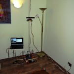
Scanoman ready for action

Scanoman ready for action

When I started the Scanoman project early this year, the following main requirements were considered:

  • Very affordable – for anyone who would like to have/build one;
  • Easily doable – by anyone who has minimal knowledge, experience and tools;
  • 3D printable – for as many parts as possible;
  • Lightweight and portable – so that one can take it here and there;
  • Simply usable – by anyone having some technical common sense.

At the time, there was (and still is) little information available about building a full body scanner in a DIY style. Therefore, I decided the design would have to become open source so that anyone could get inspired and make one.

Professional studios opted for multiple cameras taking snapshots of the subject from various angles and then compiling the data into a 3D model. This was obviously not an option for the project.

The hobbyist strategy was to use an inexpensive sensor, normally dedicated to game consoles, mount it on a pole, and have the subject being scanned when standing on a rotating turntable in front of the sensor.

The later appeared to be a reasonable approach for my purpose.
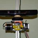
Microsoft Kinect for XBOX sensor mounted on Scanoman

Microsoft Kinect for XBOX sensor mounted on Scanoman

Microsoft Kinect for XBOX was the sensor of choice. It was the cheapest available and I could buy it from a general electronic equipment store, which very well complied with the requirements. I was aware that this would be at the cost of lower quality, since the senzor resolution and accuracy are very, very basic, but was a good starting point.

The long connection cable was an advantage. Since the sensor would have to go up and down on the pole, having a continuous cable was a plus.

The sensor is mounted on a slider that is driven by a NEMA 17 stepper motor through a reduction gearing, which pinion is running on a rack along the vertical pole. Using a rack was a simple way to solve the requirement of having the pole composed by individual segments, so it can be easily assembled and disassembled.

The sensor could also be tilted. I didn’t find a quick and easy way to use the internal motor of the senzor, so I used yet another stepper motor mounted on the slider. I discovered later on that you do not actually need too much this function.
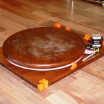
40 cm turntable driven by a NEMA 17 stepper motor

40 cm turntable driven by a NEMA 17 stepper motor

The turntable construction required to solving many engineering issues.

After considering various alternatives, I went for the one that could be built from easy to find parts. It uses a round worktop that I found in the hardware store in 40, 60 and 80 cm diameter. I took the smallest one, which would suffice in most cases for single person scanning, and mount eight 626 bearings underside, so it could spin around a central axis. While each bearing would have to support more that 10 kg each, I placed a 1 mm steel sheet on top of the base plate (which is a 40 x 50 x 18 cm hard wood board).

The most challenging part was to drive the turntable. After many trials, I came to the optimal configuration in respect to speed, power and… cost. Using a simple NEMA 17 stepper motor, a reduction gearing and a 300-tooth “circular rack” was enough to obtain a full rotation of an 160 kg load in 20 seconds!
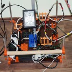
Main plate with pole mounting, controller, power and wiring

Main plate with pole mounting, controller, power and wiring

Having the sensor sliding along a 2.5 m height pole made from aluminum square tube (this was easier to found and cheaper than T-slot bars), cut in 5 segments, and the turntable easily rotating with one person standing on it have solved most of the construction issues.

A second hard wood board was used to mount the pole, the power supply, the controller, an USB hub and all the mountings used to hold parts of the scanner while disassembled.

Scanoman uses a controller designed for 3D printers, as it has to drive 3 stepper motors, sense 2 endstops, and also turn on and off the supplementary spotlights. And software-wise, it is controlled through the very well known (in the 3D printing reprap world) application called Pronterface. This was once again a proof that 3D scanning and 3D printing go hand in hand!
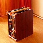
Scanoman packed and ready to go

Scanoman packed and ready to go

As intended, Scanoman is portable.

It could be easily (dis)assembled in a quarter of an hour, using just a small screwdriver to fix the pole segments.

I have to admit that this version is not so light as I would liked too, weighting some 15 kg! Good news is that I identified means by which the total weight could be reduced by half!

Scanoman already traveled in Bucharest and is expecting more opportunities to do his job, which is, no wonder, to scan people. While some people might be happy to come to a scanning studio, others will prefer to being scanned at home. Or you can take it with you when going to a party and scan the participants!

3D selfie of Vali

3D selfie of Vali

When it came to 3D scanning software the choice was not less than obvious: ReconstructMe!

It is by far the most user-friendly, rapidly evolving and almost free 3D scanning application.

ReMe does the job very well and fast. And it’s also fashionable. Want to have a 3D selfie? Nothing simpler, you get a ready to be printed bust model of yourself, at a click of the mouse (well, with Scanoman is really as such!)

3D scanning becomes a very very simple task. Perhaps the only single thing you have to carefully consider is lighting. You should have a uniform and indirect lighting of the subject, of adequate white tone and intensity, or you can easily get artifacts on your model (this may explain why Vali, my wife, does not seem to be vary happy in her 3D selfie).
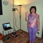
Scanoman and Vali saying bye-bye

Scanoman and Vali saying bye-bye

And, yes, you need a more than decent computer, but not necessarily a top edge one. I’m using an Acer Aspire V3 which works very well and its price tag is well below 1000 EUR.

When it comes to money, if we put aside the sensor, Scanoman cost would be below 250 EUR, including all materials, electronics, motors, etc. Well, it will take some time to build one, but this is fun, lots of fun! And, as promised, Scanoman is open source.

Coming up next is a new version of Scanoman. It will focus on optimizing the construction, reducing weight and improving usage. Then more thoughts should be given to performance and quality.

You may want to keep an eye on that, by following 3Dmaker4U on the websiteFacebookYouTubeor LinkedIn.

3Dmaker4U is an initiative that is aimed to promoting and developing 3D technologies, such as 3D printing, 3D scanning and 3D modelling, and their applications.

Bye-bye for now and enjoy the short Scanoman introductory video below!

ReconstructMe Large Scale Reconstruction – Development Insights

Recently we kicked off the development of a new feature. Large scale reconstruction. Our vision is to enable users to reconstruct large areas with low cost sensors on mobile devices. This post shows the initial developments in boundless reconstruction.

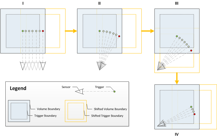
Many approaches could be applied to enable this feature. After an evaluation we finally decided for a solution which integrates nicely into ReconstructMe. That is, we translate the volume along canonical directions and keep track of the camera position in world space. Once we determine how to shift, we need to figure out when to shift.

We decided to go with the concept of what we call trigger boundaries that are relative to the volume. When a specific point crosses this boundary, the volume will be shifted. The first approach was to position the camera at the center of the volume. Once the camera position crossed the boundary, the volume was shifted. We found that this concept did not perform ideally, since the data behind the camera is allocated but most likely not captured and thus wasteful. After evaluating different options, we settled with the idea to specify the trigger point as the center of the view frustum in camera space. Again, when the trigger point crosses the trigger boundary the volume is shifted into the dimension of the cross occurence.

LargeScaleVolumeShift

In testing we faced the issue that ReconstructMe requires decent computation hardware and its rather tedious to move around with a full blown desktop PC or gamer notebook. Luckily, a old feature called file sensor helped us to speed up testing and data acquisition. Recording a stream of a depth camera does not require a lot of hardware resources and can be performed on Windows 8 tablets (Asus Transformer T100 in this case).

The streams were used to test the approach and to extract a colorized point cloud of the global scanned area. The tests showed a drift of the camera which was expected. Nonetheless, ReconstructMe is able to reconstruct larger areas without any problems if enough geometric information is available.

Based on our initial experiences, we plan to invest into more research in robust camera tracking algorithms, loop closure detection and mobility. Additionally we will need to settle with a workflow for the user interface and at the SDK level.


Job Offer: Software developer

Thanks to the success of many of our projects like ReconstructMe and CANDELOR, we are now looking to expand our team! If you are an ambitious software engineer who knows how to develop and structure complex software and are interested to develop cutting edge technology, apply here (in German):

Software Entwickler für „Components of Vision“ (m/w)

Know someone who might be interested? Please let them know!

Relases of ReconstructMe 1.2 and ReconstructMe SDK 1.5

We’ve released new versions of ReconstructMe (ReconstructMeQt in previous versions) and ReconstructMe SDK. Were happy to introduce OpenNi 2 with this release. We decided to remove the sensor driver installer option from the installer of ReconstructMe and ReconstructMe SDK, since there is only either the Asus sensor driver necessary, or the Microsoft SDK v1.6.
The new SDK provides a faster and more memory efficient polygonization routine. ReconstructMe generally got faster and easier to handle. Feel free to check out the new version and test it.

ReconstructMeQt and Speech Recognition

If you are using ReconstructMeQt on a Windows 7 PC, you will be happy to hear that our application can be controlled by speech commands, essentially freeing you from having your fingers at the keyboard while scanning. Here is how it works.

Most sensors carry single microphones or an entire microphone-array. Using Windows speech recognition one can translate spoken commands to key-press events. We’ve created a speech recognition macro file that maps the following voice commands to keystrokes:

  • ReconstructMe Start – CTRL+P
  • ReconstructMe Stop – CTRL+P
  • ReconstructMe Reset – CTRL+R
  • ReconstructMe Save – CTRL+S

The following PDF file contains has the required instructions for setting this up.[wpdm_file id=76]
The speech recognition macro can be downloaded from the link below.[wpdm_file id=75]

Have fun reconstructing!
Online 3D Viewer

A while ago, I’ve posted a scan of myself on SketchFab. The nice thing about it is that it is possible to integrate a 3D viewer in your browser:

This should work with any modern browser.

The Hives at MakerBot

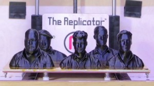
None other than the swedish rock band The Hives visited MakerBot where they got 3D reconstructed using ReconstructMe and 3D printed by the Replicator. There is a blog post on Thingsinverse where the models can be downloaded from.

Thanks to Baeble Music, there is also a video available. Enjoy :-)

ReconstructMe and ASUS at the Computer Graphics Workshop 2012 in Taipei

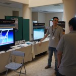
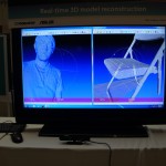
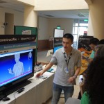
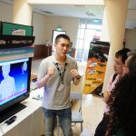
ASUS demonstrated ReconstructMe with their sensor Xtion Pro at the Computer Graphics Workshop 2012 helded by ACM SIGGRAPH in Taipei (2012/07/12 – 2012/07/13). Below, you can see some impressions of the workshop.

Scan of a Nissan Qashqai using Volume Stitching

A few days ago we tested our new feature volume stitching which enables the rough alignment of multiple volumes. We did a quick scan of a car using 1.5m sized volumes. What you can see below is the raw output of ReconstructMe without any filtering or post processing, except slightly repositioning of one of the volumes. We made up a promo video demonstrating the process and the results:

As you can see, ReconstructMe is running on a laptop and we are using the Asus Xtion Pro Live for better mobility and flexibility in scanning. We have a quite big release in the queue featuring among other things

  • Volume stitching
  • 3D Surface preview
  • PLY file support

Stay tuned.

ReconstructMe with Glasses

Inspired by ideas of MagWeb, Tony Buser has done an awesome glasses mod with the Kinect and ReconstructMe. He got +2.5 reading glasses and fixed them in front of the kinect. It is a bit difficult to get a complete scan with these as the image is distored, but the result looks really excellent:


The mod looks really cool, I am amazed that this actually works… It definitely shows that adding a lens to the Kinect might be a good solution to be able to scan small parts. The difficult part will be to provide a calibration method that can successfully undistort the data.

Here are the settings Tony Buser has used for this scan:

camera_size_x: 640
camera_size_y: 480
camera_fx: 514.16
camera_fy: 514.16
camera_px: 320
camera_py: 240
camera_near: 100
camera_far: 2000
volume_size: 512
volume_min {
x: -250
y: -250
z: 400
}
volume_max {
x: 250
y: 250
z: 900
}
integrate_truncation: 10
integrate_max_weight: 64
icp_max_iter: 20
icp_max_dist2: 200
icp_min_cos_angle: 0.9
smooth_normals: false
disable_optimizations: false
extract_step_fact: 0.5

Character Creation with a ReconstructMe Scan

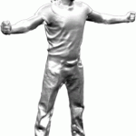
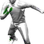
We have created a full body scan one of our coworkers while using a bigger volume, and he used this as the basis for a character animation.

  1. The most difficult part of the scanning process was to stand still and not move the arms. We solved this problem by letting the model hold a broomstick in each hand :) This data was later removed from the CAD scan.
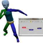
  2. To animate the skin of the character a biped system from 3Ds Max was used.
  3. Finally, With Motion Mixer from 3Ds Max, several BIP files were loaded to affect biped motion.

The result looks quite stunning! Here is a video with the result:

Here are some more screenshots: